Next | Prev | Up | Top | Contents | Index
VMEbus Channel Adapter Module (VCAM) Board
The VCAM board provides the interface between the Ebus and the VMEbus and manages the signal level conversion between the two buses. The VCAM also provides a pass-through connection that ties the graphics subsystem to the Ebus.
The VCAM can operate as either a master or a slave. It supports DMA-to-memory transactions on the Ebus and programmed I/O (PIO) operations from the system bus to addresses on the VMEbus. In addition, the VCAM provides virtual address translation capability and a DMA engine that increases the performance of non-DMA VME boards.
VMECC
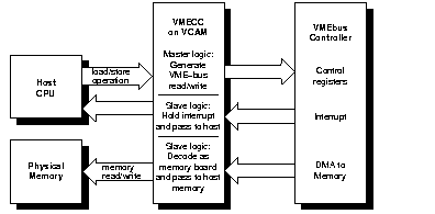
The VMECC (VME Cache Controller) gate array is the major active device on the VCAM. The VMECC interfaces and translates host CPU operations to VMEbus operations (see Figure 13-2). The VMECC also decodes VMEbus operations to translate them to the host side.

Figure 13-2 : VMECC, the VMEbus Adapter
The VMECC provides the following features:
- an internal DMA engine to speed copies between physical memory and VME space (see "Operation of the DMA Engine")
- a 16-entry deep PIO FIFO to smooth writing to the VME bus from the host CPUs
- a built-in VME interrupt handler and built-in VME bus arbiter
- an explicit internal delay register to aid in spacing PIOs for VME controller boards that cannot accept back-to-back operations
- support for issuing A16, A24, A32, and A64 addressing modes as a bus master during PIO
- support for single-item transfers (D8, D16, D32, and D64) as a bus master during PIO
- support for response as a slave to A24, A32, and A64 addressing modes to provide DMA access to the Ebus
- support for single-item transfers (D8, D16, and D32) as a slave during DMA access to the Ebus
- support for block item transfers (D8, D16, D32, and D64) as a slave during DMA access to the Ebus
The VMECC also provides four levels of VMEbus request grants, 0-3 (3 has the highest priority), for DMA arbitration. Do not confuse these bus request levels with the interrupt priority levels 1-7. Bus requests prioritize the use of the physical lines representing the bus and are normally set by means of jumpers on the interface board.
F Controller ASIC
Data transfers between VME controller boards and the host CPU(s) takes place through the VMECC on the VCAM board, then through a flat cable interface (FCI), and onto the F controller ASIC.
The F controller acts as an interface between the Ibus and the Flat Cable Interfaces (FCIs). This device is primarily composed of FIFO registers and synchronizers that provide protocol conversion and buffer transactions in both directions and translate 34-bit I/O addresses into 40-bit system addresses.
Two configurations of the F controller are used on the IO4 board; the difference between them is the instruction set they contain. One version is programmed with a set of instructions designed to communicate with the GFXCC (for graphics); the other version has instructions designed for the VMECC. All communication with the GFXCC or VMECC ICs is done over the FCI, where the F controller is always the slave.
Both versions of the F controller ASICs have I/O error-detection and handling capabilities. Data errors that occur on either the Ibus or the FCI are recorded by the F controller and sent to the VMECC or GFXCC.
ICs must report the error to the appropriate CPU and log any specific information about the operation in progress. FCI errors are recorded in the error status register. This register provides the status of the first error that occurred, as well as the cause of the most recent FCI reset.
VMEbus Interrupt Generation
The VME bus supports seven levels of prioritized interrupts, 1 through 7 (where 7 has the highest priority). The VMECC has a register associated with each level. When the system responds to the VMEbus interrupt, it services all devices identified in the interrupt vector register in order of their VMEbus priority (highest number first). The following list outlines how a VMEbus interrupt is generated:
- A VME controller board asserts a VME interrupt on one of the IRQ levels.
- The built-in interrupt handler in the VMECC chip checks if the interrupt level is presently enabled by an internal interrupt mask.
- The interrupt handler in the VMECC issues a bussed IACK (interrupt acknowledge) response and acquires the vector from the device. The 3-bit response identifies one of the seven VME levels.
- If multiple VME boards are present, the bussed IACK signal is sent to the first VME controller as an IACKIN. When the first controller is not the requesting master, it passes the IACKIN signal to the next board (in the daisy-chain) as IACKOUT.
- The requesting board responds to IACKIN by issuing a DTACK* (data acknowledge signal), blocking the IACKOUT signal to the next board, and placing an 8-bit interrupt vector number on the data bus.
- The VMECC latches the interrupt vector, and an interrupt signal is sent over the FCI interface to the F-chip and is queued awaiting completion of other F-chip tasks.
- The F controller ASIC requests the I-bus and sends the interrupt to the IA chip.
- The IA chip requests the Ebus and sends the interrupt over the Ebus to the CC chip on the IP19/IP21 board.
- The CC chip interrupts the R4400/R8000, provided that the interrupt level is not masked.
The time for this to complete is normally less than 3 microseconds, but will be queued to await completion of other VME activities.
Next | Prev | Up | Top | Contents | Index

